


Applications
Contact us
Spiroflex d.o.o.
Ljudevita Gaja 7
35 208 Ruščica
Croatia
Phone: +385 35 212 432
e-mail: info@spiroflex.hr
Lateral expansion joints for pump applications
Introduction
Pumps, compressors, hydrodynamic engines and similar aggregates generate vibrations and noise which is transferred transfer to pipelines, installations and equipment. Bellows pump connectors are designed as bellows with several thin sheets instead of thick one. Multi-ply design permits a lower spring rate and maintains a high flexibility. They are recommended for application with vibration and rapid cyclic motion.
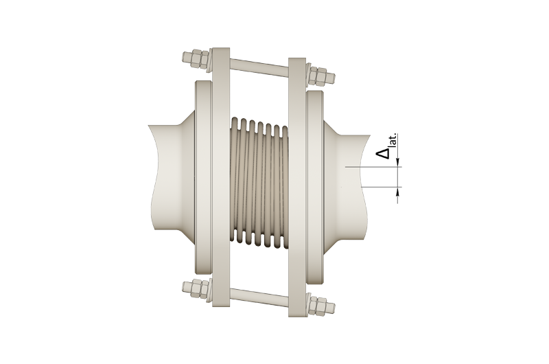
Movements
These bellows absorb only lateral movements in all directions and they are not convenient for axial movements
Structure of lateral expansion joint
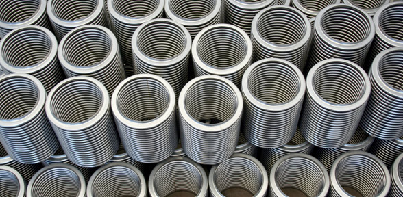
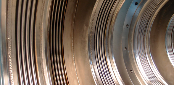
Bellows
- Materials: DIN EN 1.4541 ili 1.4571
- Multi-ply laminated bellows
- Bellows welded on flanges or expansion joint with loose flanges
Flanges
- Materials: Carbon steel or stainless steel
- Welded or loose flanges
Tie roads
- Carbon steel or stainless steel
Application
- Reduction of tension, vibrations, stresses on pumps, compressors, turbines, engines and burners
- For small inaccuracies between pipeline and pump or other equipment
- For compensation of misalignment foundation settlement and assembly movement
- Installation in gas and water supply systems
- Installation in heating, ventilation and climate system
- Installation in drinking water systems and waste water plant treatment
- Lateral expansion joints absorb small thermal movements of pipeline and equipment

Lateral expansion joint with fixed flanges

Lateral expansion joint with loose flanges
Advantages of lateral expansion joints
- Pressure and temperature resistance
- Flexibility
- Quick and easy installation
- Corrosion resistance
- Vacuum resistance
- Operating safety
- Long service life
- No maintenance

Lateral expansion joints on aggregate

Pressure balanced expansion joint on aggregate

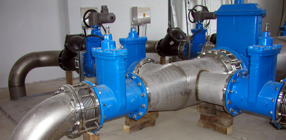
Lateral expansion joints on pump
Installation
The expansion joint should be positioned on the aggregate flange. Spiroflex recommends installation of fix point as close as possible after expansion joint. With installation of fix point the pipeline will be protected from vibrations and noise.
Lateral expansion joints
Typ: STF

PN10 Project pressure – standard program
| NO | Lateral movement | Install length | Lateral spring rate | Gasket surface | Outside dia. | Flange height | Flange thickness | Mass | |
| Total mm | ±mm | L mm |
N/mm | d4 mm |
ØDa mm |
H mm |
b mm |
kg | |
| 40 | 16 | 8 | 105 | 47 | 88 | 65 | 220 | 18 | 9 |
| 50 | 17 | 8,5 | 130 | 39 | 102 | 80 | 240 | 19 | 11 |
| 65 | 18 | 9 | 145 | 50 | 122 | 96 | 260 | 20 | 13 |
| 80 | 16 | 8 | 140 | 55 | 138 | 115 | 280 | 22 | 16 |
| 100 | 18 | 9 | 170 | 91 | 158 | 140 | 295 | 25 | 20 |
| 125 | 16 | 8 | 180 | 158 | 188 | 168 | 340 | 28 | 24 |
| 150 | 14 | 7 | 180 | 265 | 212 | 195 | 370 | 28 | 24 |
| 200 | 10 | 5 | 195 | 625 | 268 | 260 | 465 | 32 | 30 |
| 250 | 8 | 4 | 200 | 1210 | 320 | 315 | 520 | 35 | 36 |
| 300 | 10 | 5 | 240 | 2205 | 370 | 380 | 625 | 40 | 48 |
Table data refer to conditions +20°C, material of bellows DIN EN 1.4541, 1.000 full cycles. For special request please provide inquiry.
PN16 Project pressure – standard program
| NO | Lateral movement | Install length | Lateral spring rate | Gasket surface | Outside dia. | Flange height | Flange thickness | Mass | |
| Total mm | ±mm | L mm |
N/mm | d4 mm |
ØDa mm |
H mm |
b mm |
kg | |
| 40 | 16 | 8 | 110 | 74 | 88 | 65 | 220 | 18 | 40 |
| 50 | 16 | 8 | 125 | 37 | 102 | 80 | 240 | 19 | 50 |
| 65 | 16 | 8 | 140 | 82 | 122 | 96 | 275 | 20 | 65 |
| 80 | 18 | 9 | 160 | 126 | 138 | 117 | 290 | 22 | 80 |
| 100 | 18 | 9 | 180 | 142 | 158 | 144 | 310 | 25 | 100 |
| 125 | 16 | 8 | 185 | 295 | 188 | 175 | 375 | 28 | 125 |
| 150 | 13 | 6,5 | 185 | 490 | 212 | 205 | 410 | 28 | 150 |
| 200 | 10 | 5 | 195 | 975 | 268 | 260 | 465 | 32 | 200 |
| 250 | 8 | 4 | 210 | 1825 | 320 | 310 | 590 | 40 | 250 |
| 300 | 9 | 4,5 | 230 | 3720 | 378 | 385 | 670 | 40 | 300 |
Table data refer to conditions +20°C, material of bellows DIN EN 1.4541, 1.000 full cycles. For special request please provide inquiry.